- 您现在的位置:买卖IC网 > Sheet目录1993 > DS1388Z-3+T&R (Maxim Integrated Products)IC RTC I2C W/CHARGER 8-SOIC
I2C RTC/Supervisor with Trickle Charger
and 512 Bytes EEPROM
Maxim Integrated
11
DS1388
ADDRESS
BLK
WORD
BIT 7
BIT 6
BIT 5
BIT 4
BIT 3
BIT 2
BIT 1
BIT 0
FUNCTION
RANGE
0h
00h
Tenth Seconds
Hundredths of Seconds
Hundredths of
Seconds
00–99
0h
01h
0
10 Seconds
Seconds
00–59
0h
02h
0
10 Minutes
Minutes
00–59
AM/
PM
10 Hour
0h
03h
0
12/24
10 Hour
Hours
1–12+
AM/PM
00–23
0h
04h
0
X
Day
01–07
0h
05h
0
10 Date
Date
01–31
0h
06h
0
X
10
Month
01–12
0h
07h
10 Year
Year
00–99
0h
08h
Watchdog Tenths of Seconds
Watchdog Hundredths of Seconds
Watchdog
Hundredth
Seconds
00–99
0h
09h
Watchdog Ten Seconds
Watchdog Seconds
Watchdog
Seconds
00–99
0h
0Ah
TCS3
TCS2
TCS1
TCS0
DS1
DS0
ROUT1
ROUT0
Trickle Charger
—
0h
0Bh
OSF
WF
0
Flag
—
0h
0Ch
EOSC
0
WDE
WD/RST
Control
—
1h
00–FFh
256 x 8 EEPROM
EEPROM
00–FFh
2h
00–FFh
256 x 8 EEPROM
EEPROM
00–FFh
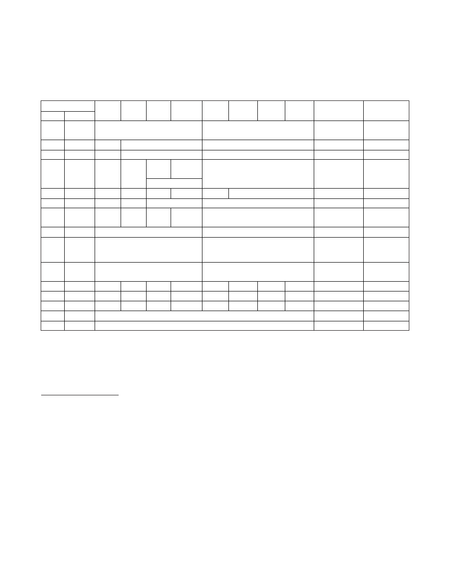
Figure 4. Address Map
Note: Unless otherwise specified, the state of the registers is not defined when power (VCC and VBACKUP) is first applied.
X = General-purpose read/write bit.
0 = Always reads as a zero.
Clock and Calendar
The time and calendar information is obtained by read-
ing the appropriate register bytes. Figure 4 illustrates
the RTC registers. The time and calendar are set or ini-
tialized by writing the appropriate register bytes. The
contents of the time and calendar registers are in the
binary-coded decimal (BCD) format. The end of the
month date is automatically adjusted for months with
fewer than 31 days, including corrections for leap years
through 2099. The day-of-week register increments at
midnight. Values that correspond to the day-of-week
are user-defined but must be sequential (i.e., if 1
equals Sunday, then 2 equals Monday, and so on).
Illogical time and date entries result in undefined oper-
ation. The DS1388 can be run in either 12-hour or 24-
hour mode. Bit 6 of the hours register is defined as the
12- or 24-hour mode-select bit. When high, the 12-hour
mode is selected. In the 12-hour mode, bit 5 is the
AM/PM bit with logic-high being PM. In the 24-hour
mode, bit 5 is the 20-hour bit (20–23 hours). Changing
the 12/24 bit requires that the hours data be re-entered
in the proper format.
发布紧急采购,3分钟左右您将得到回复。
相关PDF资料
DS1391U-3+
IC RTC W/CHARGER 10-USOP
DS1394U-33+T&R
IC RTC SPI 3WIRE W/CHRGR 10-MSOP
DS14285SN+T&R
IC RTC W/NV RAM CNTRL 24-SOIC
DS1486P-120+
IC TIMEKEEPER RAM 1MB 34-PCM
DS1500WE
IC RTC Y2KC W/NV CTRL 32-TSOP
DS1501YSN+T&R
IC RTC WDOG Y2K 5V IND 28-SOIC
DS1553P-70+
IC RTC RAM Y2K 5V 70NS 34-PCM
DS1554W-120IND
IC RTC RAM Y2K 3.3V 120NS 32EDIP
相关代理商/技术参数
DS1388Z-33
功能描述:实时时钟 RoHS:否 制造商:Microchip Technology 功能:Clock, Calendar. Alarm RTC 总线接口:I2C 日期格式:DW:DM:M:Y 时间格式:HH:MM:SS RTC 存储容量:64 B 电源电压-最大:5.5 V 电源电压-最小:1.8 V 最大工作温度:+ 85 C 最小工作温度: 安装风格:Through Hole 封装 / 箱体:PDIP-8 封装:Tube
DS1388Z-33+
功能描述:实时时钟 I2C RTC/Supervisor w/Trickle Charger RoHS:否 制造商:Microchip Technology 功能:Clock, Calendar. Alarm RTC 总线接口:I2C 日期格式:DW:DM:M:Y 时间格式:HH:MM:SS RTC 存储容量:64 B 电源电压-最大:5.5 V 电源电压-最小:1.8 V 最大工作温度:+ 85 C 最小工作温度: 安装风格:Through Hole 封装 / 箱体:PDIP-8 封装:Tube
DS1388Z-33+T&R
制造商:Maxim Integrated Products 功能描述:REAL TIME CLOCK SERL 512BYTE 8SOIC - Tape and Reel 制造商:Maxim Integrated Products 功能描述:MXMDS1388Z-33+T&R I?2C RTC/SUPERVISOR WIT 制造商:Maxim Integrated Products 功能描述:IC RTC I2C W/CHARGER 8-SOIC
DS1388Z-33+T&R
功能描述:实时时钟 I2C RTC/Supervisor w/Trickle Charger RoHS:否 制造商:Microchip Technology 功能:Clock, Calendar. Alarm RTC 总线接口:I2C 日期格式:DW:DM:M:Y 时间格式:HH:MM:SS RTC 存储容量:64 B 电源电压-最大:5.5 V 电源电压-最小:1.8 V 最大工作温度:+ 85 C 最小工作温度: 安装风格:Through Hole 封装 / 箱体:PDIP-8 封装:Tube
DS1388Z-5
功能描述:实时时钟 RoHS:否 制造商:Microchip Technology 功能:Clock, Calendar. Alarm RTC 总线接口:I2C 日期格式:DW:DM:M:Y 时间格式:HH:MM:SS RTC 存储容量:64 B 电源电压-最大:5.5 V 电源电压-最小:1.8 V 最大工作温度:+ 85 C 最小工作温度: 安装风格:Through Hole 封装 / 箱体:PDIP-8 封装:Tube
DS1388Z-5+
功能描述:实时时钟 I2C RTC/Supervisor w/Trickle Charger RoHS:否 制造商:Microchip Technology 功能:Clock, Calendar. Alarm RTC 总线接口:I2C 日期格式:DW:DM:M:Y 时间格式:HH:MM:SS RTC 存储容量:64 B 电源电压-最大:5.5 V 电源电压-最小:1.8 V 最大工作温度:+ 85 C 最小工作温度: 安装风格:Through Hole 封装 / 箱体:PDIP-8 封装:Tube
DS1390
制造商:MAXIM 制造商全称:Maxim Integrated Products 功能描述:Low-Voltage SPI/3-Wire RTCs with Trickle Charger
DS1390_07
制造商:MAXIM 制造商全称:Maxim Integrated Products 功能描述:Low-Voltage SPI/3-Wire RTCs with Trickle Charger